DRAWING-LED FASTENERS
Anchor Cages
Coordinated anchor rods and plates for wind turbine foundations and project-specific anchoring layouts.
SPECIFICATIONS & CUSTOMIZATION
Define The Geometry.
Define the rod arrangement, plate geometry and assembly tolerances as one coordinated system.
Dimensions & Configuration
- Cage Height · H
- Rod length and assembled height to the foundation drawing
- Bolt Circle · PCD
- Rod centres positioned on the specified pitch circle
- Rod Quantity · n
- Number of rods and angular spacing to the approved layout
- Rod Diameter · d
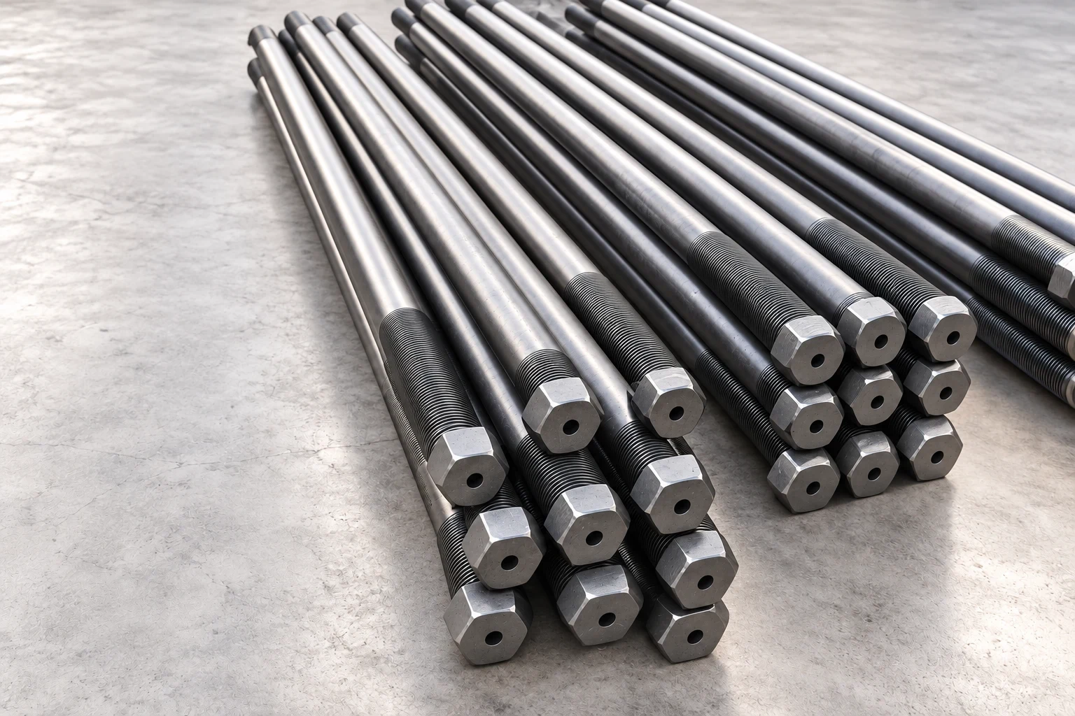
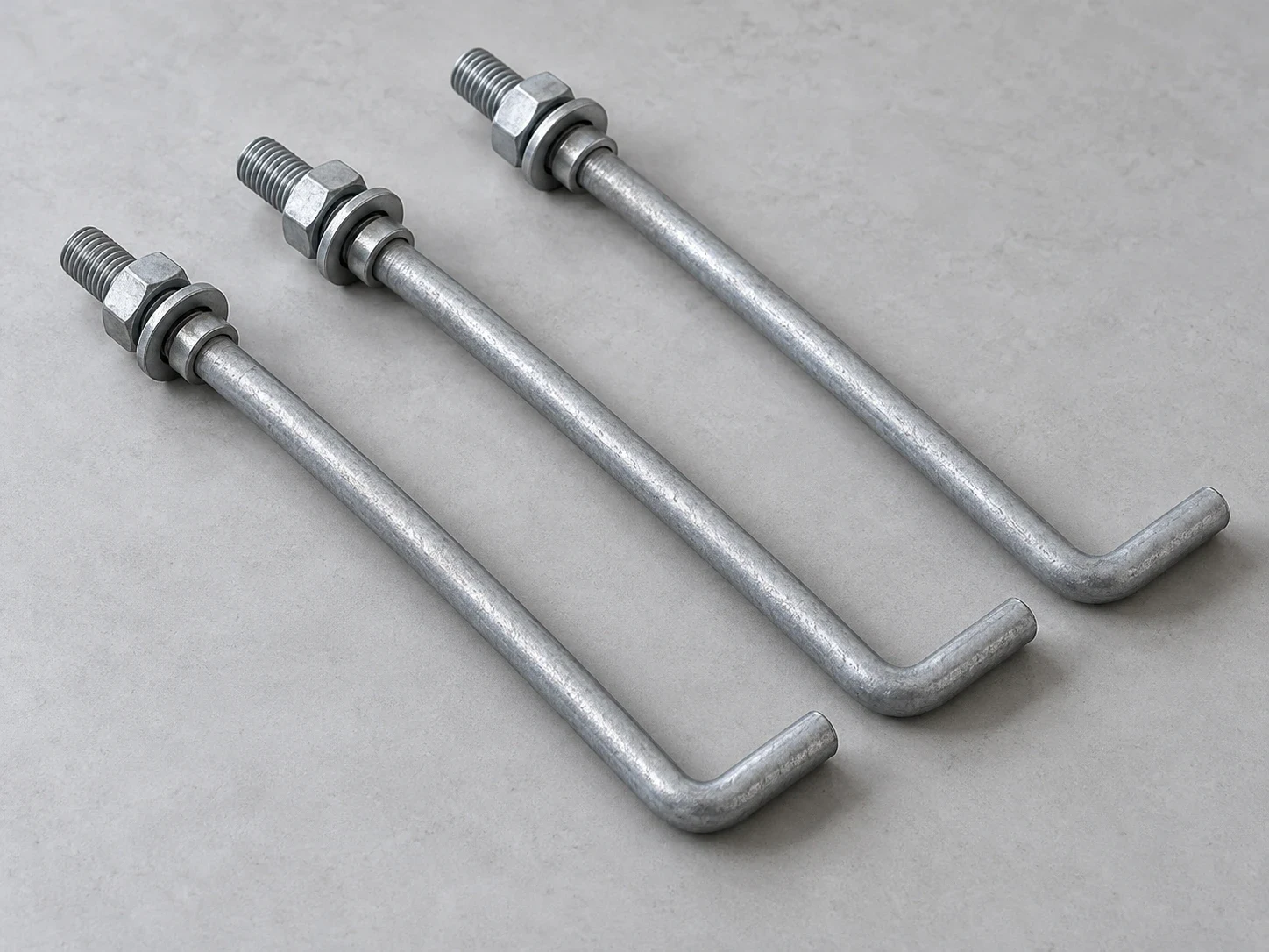
- Specify rod diameter, grade and threaded ends
- Plate Geometry
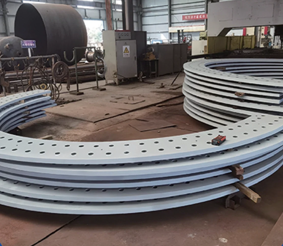
- Outer / inner diameter, thickness and hole pattern
Rods & Plates
35CrMoA / 42CrMoA rod options with Q235 / Q345 plate options. Define grades and component quantities in the bill of materials.
Assembly & Alignment
Confirm plate separation, bolt-circle alignment, rod verticality and the permitted assembly tolerances.
Finish & Protection
Specify the finish for rods and plates separately, including coated areas, exposed threads and transport protection.
COMPONENTS & INSPECTION
Plan The Complete Cage Assembly.
Supply Configuration
Define whether the order is for matched components, a partially assembled unit or a complete cage.
- Anchor rods with specified threaded ends
- Anchor / template plates, nuts and washers
- Assembly, identification and transport arrangement
Assembly Inspection
Agree the acceptance criteria against the foundation layout and component drawings.
- Rod count, bolt circle and hole alignment
- Cage height, plate separation and verticality
- Threads, material records and coating requirements
HAVE A DRAWING?
Let’s Review Your Anchor Cage Layout.
Send the layout drawing, rod schedule, plate details, assembly scope and required delivery date.