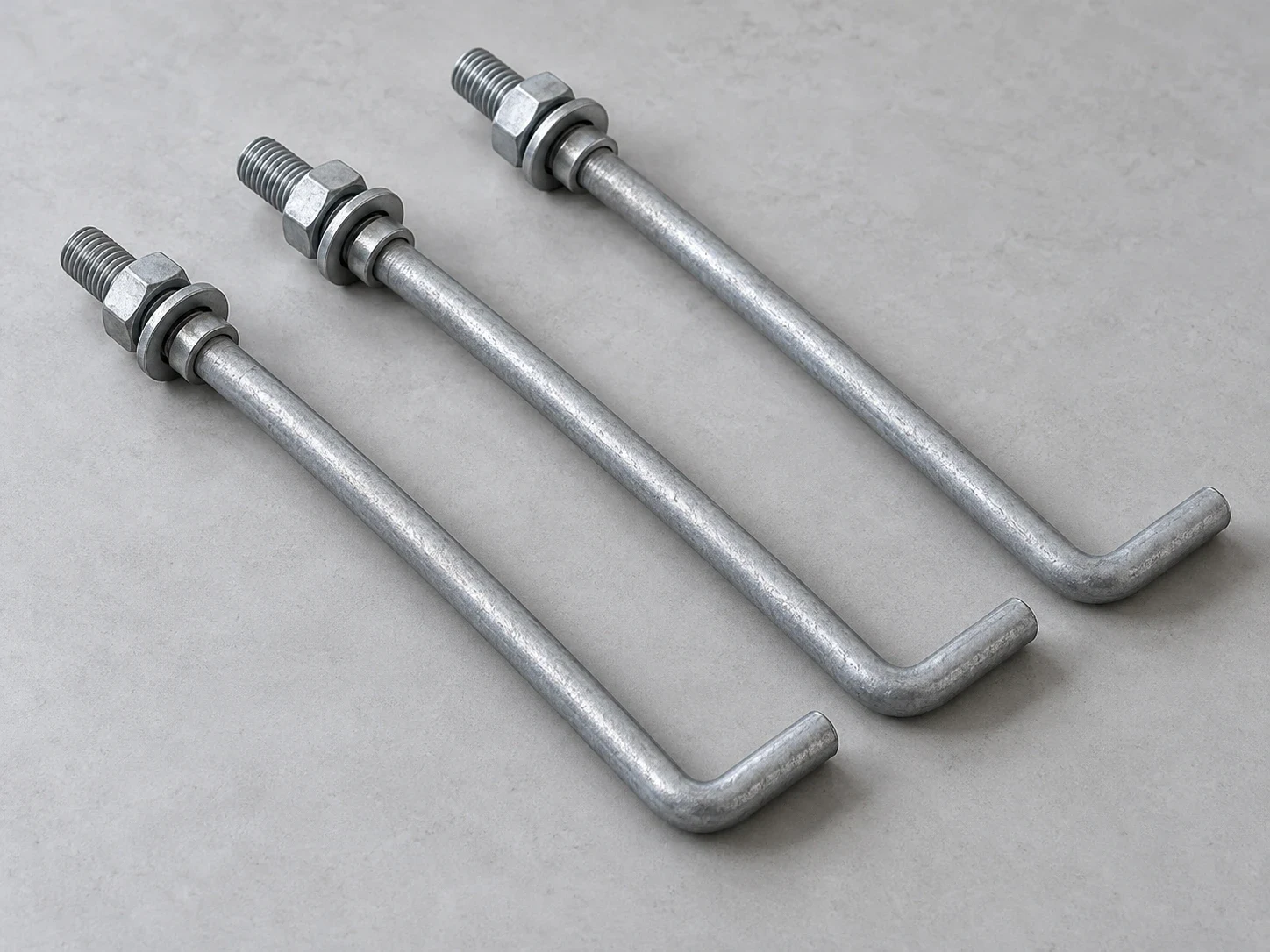
Wind turbine anchor bolts are difficult to replace once the foundation has been poured. A damaged thread can delay tower erection; an incorrectly positioned cage can require an engineered repair before installation proceeds. Problems with bolt tension may emerge later, when the turbine is already operating.
For buyers and contractors, the specification needs to cover more than steel grade and rod diameter. The connection must work as designed, arrive with verifiable documentation, and be installed without introducing avoidable stresses.
This article focuses on anchor rod systems used in concrete foundations for onshore wind turbines.
How the Foundation Connection Carries Load?
Wind loading creates an overturning moment at the tower base. This increases tension demand on one side of the foundation connection and compression on the other. The distribution changes with wind direction and turbine operation.
In a typical anchor cage, long steel rods are arranged around a bolt circle and secured through a lower anchorage assembly. Their upper ends pass through the tower base flange, where nuts and washers complete the connection.
The rods do not carry every load independently. Flange stiffness, concrete behavior, grout contact, and the anchorage detail all affect how forces move through the joint. Horizontal shear also needs a defined transfer mechanism in the design; assuming that the rods carry all of it can misrepresent the connection.
Fatigue Starts with the Connection Detail
A bolt can meet its tensile strength requirement and still perform poorly under repeated loading.
Wind turbine foundation bolts experience fluctuating loads over many operating cycles. For fatigue assessment, the stress range matters alongside the maximum stress. Thread roots and changes in section deserve particular attention because they concentrate stress.
Installation can affect this behavior. A rod pulled sideways to fit a flange hole may carry additional bending. Uneven bearing or local flange separation can also change bolt loading.
Research into wind turbine foundation anchorage considers both ultimate resistance and fatigue life. That makes bolt diameter and quantity part of a connection design, rather than standalone purchasing decisions. University of Birmingham
Material Grade Is Only Part of the Specification
“High-strength steel” is too broad for a purchase order.
The approved specification should identify the required material, mechanical properties, heat treatment, and testing. Depending on the project, this includes yield strength, tensile strength, elongation, hardness, and impact toughness at a specified temperature.
Nuts and washers need equal attention. Their properties and dimensions must suit the rod and the intended assembly.
Thread details should be stated clearly, including diameter, pitch, tolerances, and inspection requirements. Calculations for threaded sections use the relevant tensile stress area, which is smaller than the gross shank area.
A proposed material substitution needs engineering review, even when its stated strength is higher. Toughness, ductility, coating compatibility, and the basis of the original design still need checking.
Applied Torque Is Not Retained Bolt Tension
Pretension clamps the joint before the turbine enters service. When the connection is correctly designed and assembled, that clamping force helps limit separation and cyclic bolt loading.
The practical challenge is achieving the specified retained tension.
With torque tightening, friction at the threads and nut-bearing surface influences the result. Changes in lubrication or coating condition can change bolt tension at the same applied torque.
Hydraulic tensioning stretches the rod directly, but some load is lost during transfer from the tool to the nut. The procedure must account for that behavior.
Site instructions should specify calibrated equipment, the tightening sequence, acceptance criteria, and any required verification. A generic torque chart cannot establish the correct pretension for a turbine foundation.
Check the Cage Before Concrete Placement
The best time to identify a positioning error is before the pour.
Check the bolt-circle diameter, spacing, verticality, exposed length, and orientation against the approved drawings. Confirm that the template and supports can hold their position during reinforcement work and concrete placement.
Protect exposed threads from impact and concrete contamination. If the design includes sleeves or an unbonded rod length, preserve those details during installation.
Before final tensioning, verify the specified concrete and grout strengths and the required bearing condition. A correctly manufactured bolt cannot compensate for an incorrectly prepared interface.
Keep Water Out and Records Accessible
Corrosion protection needs to cover exposed threads, nuts, washers, and details where water can collect. The coating process must suit the steel and project specification, including hydrogen embrittlement considerations where applicable.
Inspection access matters after commissioning. The American Clean Power Association identifies insufficient anchor bolt pretension as a potential contributor to fatigue damage and refers maintenance checks to the foundation design requirements. ACP Foundation Maintenance Guidance
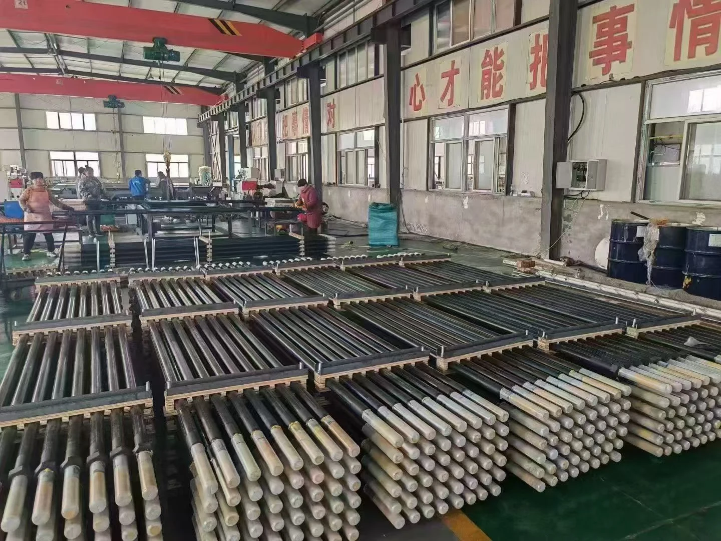
For procurement, request heat-number traceability, material certificates, specified test results, and dimensional inspection records. Packaging should protect threads while keeping component identification readable through delivery and storage.
A useful final check is straightforward: can the supplied components be traced, installed, tensioned, and inspected against the approved design? Those are stronger purchasing criteria than diameter and price alone.
Discuss Your Requirement.
Tell us what your connection needs, with or without a drawing.
Start An Enquiry